A 57-year-old male underwent a robotic assisted ventral hernia repair under general endotracheal anesthesia. This was the first case of the day and the Avance CS2 (GE Healthcare, Chicago, IL) machine passed the automated check. There was no reported malfunction of the anesthesia machine prior to this event, and induction of the patient was uneventful. Approximately one hour into the case, we noticed that the inspiratory concentration of carbon dioxide had increased and ranged between 4 and 6 mmHg. The absorbent was inspected, and although not fully spent, the absorber canister was replaced. At this time, the condenser reservoir appeared empty as shown in Figure 1, Exhibit A. Replacement of the absorber had no effect on the reported levels of carbon dioxide, and we proceeded to change the airway module D-fend water trap connected to the gas sampling line and subsequently the GE CARESCAPE Respiratory Module (GE Healthcare, Chicago, IL) without any change in the inspiratory CO2 concentration. At this point, we also noticed that the end-tidal concentration of volatile anesthetic was not consistent with the concentration being delivered. The sevoflurane vaporizer was set to 4%, yet the inspiratory concentration was significantly lower than expected at 1.6%. Intravenous anesthetic was initiated to maintain adequate minimum alveolar concentration while we continued to troubleshoot. Further inspection revealed that the fraction of inspired oxygen was reported at 21% while the anesthesia machine was set to deliver 50%. Moreover, the patient’s oxygen saturation remained within normal ranges throughout the entire procedure. Up to this moment, the fresh gas flow was set at 2 liters per minute with 50% oxygen, and we then raised the flow to 4 liters per minute at 50% oxygen with no change in measured oxygen, CO2, and agent concentrations. At this point, we contacted our biomedical team with a suspicion that the one-way valves within the circuit may have been faulty. This too was ruled out, and the valves and flow sensor were confirmed to be functioning properly. Upon consultation with another colleague, we decided to inspect the condenser reservoir more closely for water accumulation. The anesthesia machine was jostled revealing that the water line in the condenser reservoir had risen above the transparent plastic, and what visually appeared to be an empty reservoir was in fact completely filled with water as demonstrated by the air-fluid level that appeared in Figure 1, Exhibit B. The condenser reservoir was drained, and the reported measurements gradually returned to the expected values. This finding led us to conclude that the excess moisture in the circuit caused the airway module sensor to malfunction. Of note, the condenser reservoir filled completely before the end of the case and was drained a second time. We suspect that the delay in the return of accurate measurements and the speed at which the reservoir filled for a second time was due to significant moisture buildup within the circuit after the capacity of the reservoir was exceeded.
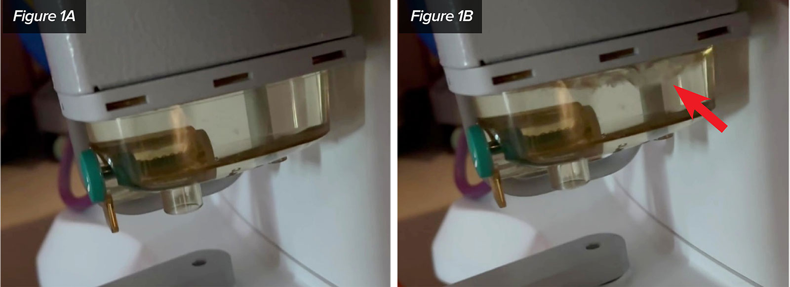
Figure 1: Exhibit A and B demonstrating the full condenser reservoir undisturbed (A) and the same condenser reservoir when shaken (B).
DISCUSSION
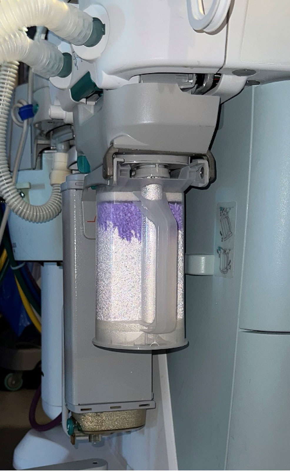
Figure 2: Location of the condenser reservoir on the Avance CS2.
We would first like to recognize that proper maintenance according to the user’s reference guide published by GE Healthcare recommends that operators visually inspect the condenser reservoir daily and drain it if needed. The condenser reservoir is located adjacent to the CO2 absorbent canister and collects water from the breathing circuit. Drainage is accomplished by pressing the green drain button on the side of the condenser and allowing the water to drain from the opening underneath.1 Appropriate maintenance is essential for the proper functioning of anesthesia equipment, and this incident further demonstrates that point. However, the aforementioned event raises several concerns regarding the location and the design of the condenser reservoir. The reservoir on the Avance CS2 is located behind the absorber canister and is only a few inches above the base of the left lateral side of the machine as seen in Figure 2. Direct access to the left side of the anesthesia machine in the operating room is often blocked by various equipment and is typically in close proximity to the sterile surgical field. Even when approached from the front of the machine, the low and posterior location of the condenser reservoir makes viewing and draining cumbersome and easily overlooked.
A further concern regarding the condenser reservoir is related to the design of the reservoir itself. With proper maintenance, water levels should never exceed the height of the transparent plastic that the reservoir is comprised of. However, as we have demonstrated, if the water level exceeds the level of the transparent plastic, the condenser reservoir may appear empty. We suggest that a consideration be made for modification of the reservoir with a means to easily determine if the reservoir contains any water. Possible modifications may include a float, the use of translucent plastic on the condenser walls, or the use of an electronic sensor that notifies the user if there is excess water accumulation in the reservoir.
Finally, our report of this incident is intended to inform the reader and create awareness amongst other users of the Avance CS2 so that issues with condenser reservoirs can be ruled out early in the troubleshooting of sensor abnormalities. We have been in contact with our local company representatives and welcome their response as well as an explanation as to how moisture affects sensor integrity.
Steven Simon is a medical student at Robert Wood Johnson University Medical School, New Brunswick, NJ.
Bryan Gaeta is a certified registered nurse anesthetist at Robert Wood Johnson University Medical School, New Brunswick, NJ.
Enrique Pantin, MD, is a professor of anesthesiology at Robert Wood Johnson University Medical School, New Brunswick, NJ.
Antonio Chiricolo, MD, is an associate professor of anesthesiology at Robert Wood Johnson University Medical School, New Brunswick, NJ.
The authors have no conflicts of interest.
REFERENCES
- GE Healthcare Avance CS2 User’s Reference Manual. Datex-Ohmeda, Inc. 2013.
- Siempos II, Vardakas KZ, Kopterides P, Falagas ME. Impact of passive humidification on clinical outcomes of mechanically ventilated patients: a meta-analysis of randomized controlled trials. Crit Care Med. 2007;35:2843–2851. PMID: 18074484
- Bhavani-Shankar K, Moseley H, Kumar AY, Delph Y. Capnometry and anaesthesia. Can J Anaesth. 1992;39:617–632. PMID: 1643689
- Fullick J, Oliver M. “Water, water, everywhere”: a challenge to ventilators in the COVID-19 pandemic. Br J Anaesth. 2020;125:e188–e190. PMID: 32389392
GE HealthCare Response:
Visual Illusion Results in Malfunction of Anesthesia Machine Sensors
March 15, 2023
Dear APSF Rapid Response,
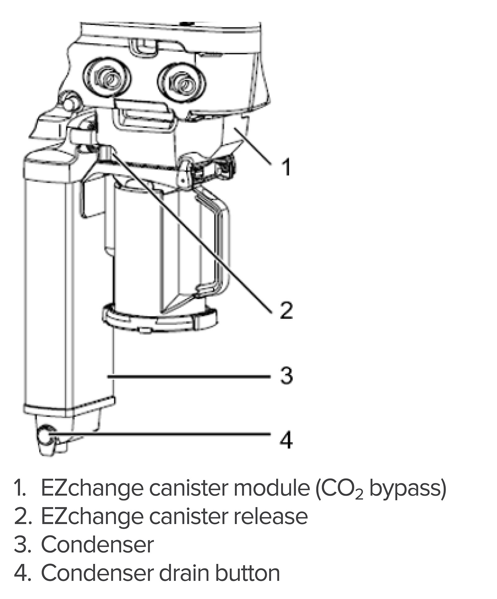
Figure 3: Condenser Location.
GE HealthCare would like to thank the team from Rutgers University/Robert Wood Johnson Medical School for submitting their experience with water accumulation and gas sampling in the Avance CS2 to the Rapid Response column. In response to this report, GE HealthCare performed extensive testing to replicate the experience described. Unfortunately, the observations could not be reproduced. Nevertheless, this report provides an opportunity to review the design features of the Avance CS2 intended to mitigate the impact of humidity in the anesthesia breathing system, and the recommended procedures for managing the challenge of water accumulation.
Managing humidity and water accumulation in the breathing system is necessary for all anesthesia systems. There are recommended strategies for minimizing water in the breathing system, as well as procedures that can be followed to eliminate the impact of water on the performance of flow and gas concentration sensors. With that goal in mind, the Avance CS2 anesthesia system includes a condenser designed into the inspiratory flow channel to control water accumulation. See Figure 3.
Adhering to the prescribed user care and maintenance instructions would minimize liquid water buildup in the condenser as observed at the Robert Wood Johnson Medical Center. When the condenser is in use and not full, condensation is visible on the walls of the condenser reservoir which serves as an indicator the reservoir is not full. See Figure 4. When condensation is not present during use, the reservoir drain should be opened to drain any accumulated water. While the condenser drain is located where it is not easily visible from a standing position, it is easily accessed from the front of the machine to visually check the water levels and drain the condenser daily. The drain is also located within close proximity to the CO2 absorber, which also is recommended to be visually examined prior to anesthetizing a patient.
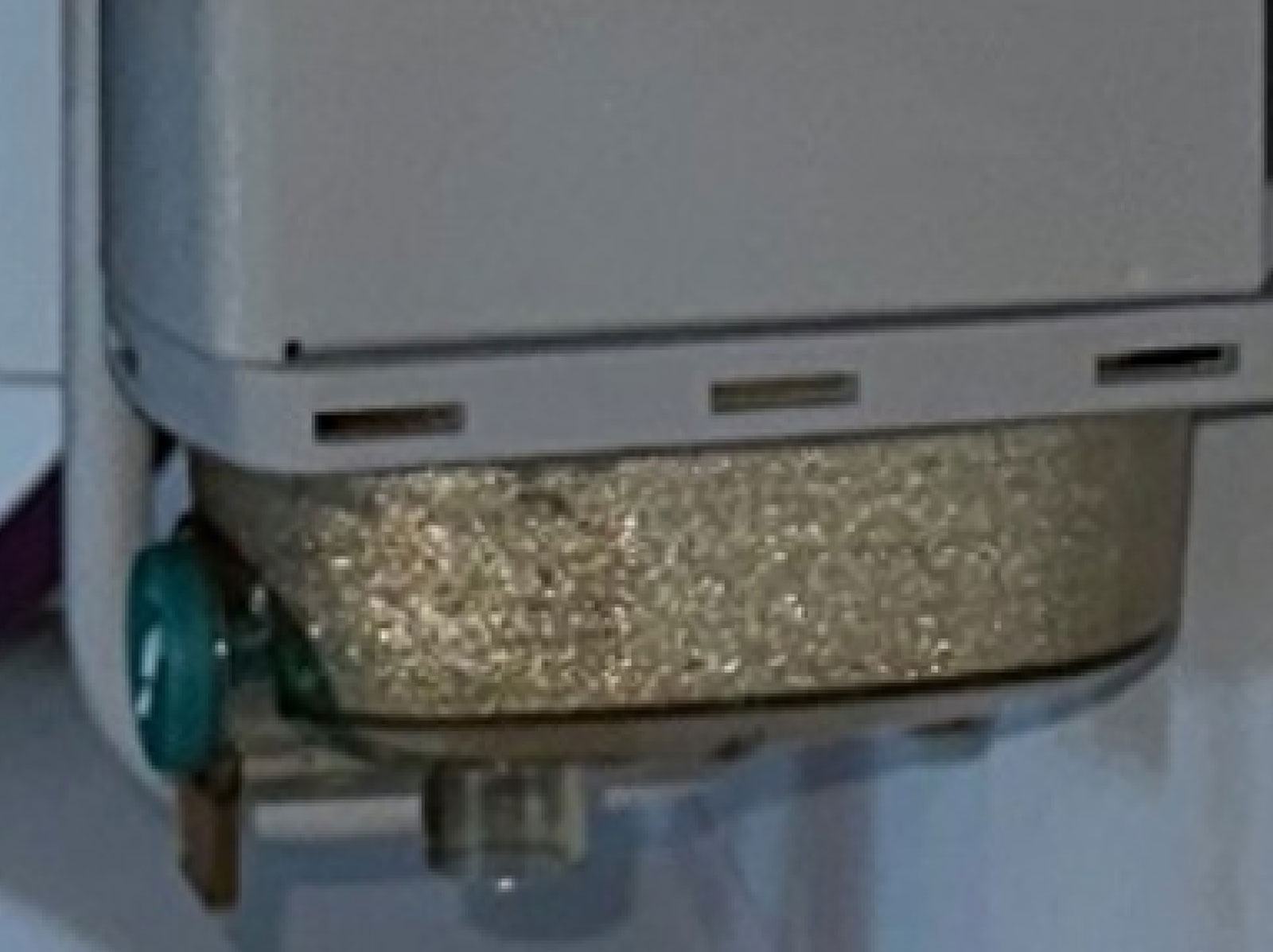
Figure 4 : Reservoir Condensation.
Consideration has been given to the additional detection methods suggested in the report by Simon et al. to improve the identification of a full reservoir, but those methods may reduce the overall reliability and simplicity of the design. If the reservoir is full, the inspiratory flow from the ventilator will simply push through the water column or bypass the reservoir completely due to bypass flow paths designed into the condenser top housing. This feature ensures that ventilation continues regardless of the water level in the reservoir. The condenser wall is designed using aluminum, as it serves as both a structural element and a heat shield to prevent the CO2 absorber heat from warming the condenser tubes.
Useful practices to minimize the impact of water on gas sampling include:
- Heat and moisture exchanger with filter (HMEF) between the patient and the breathing circuit to prevent exhaled water vapor from the patient reaching the breathing system. Even though this is considered optional as noted in the figure, it is useful for controlling water intrusion into the circuit.
- Ensure correct size and fit of accessories according to patient type and application.
- Ensure airway gas measurement setup is correct. See Figure 5.
- If using a D-lite/D-lite+ flow sensor, place all D-lite ports upwards with a 20° to 45° tilt to prevent condensed water from entering the sensor interior and tubing
- Use a D-lite+ flow sensor for high humidity conditions
- When using a mask and sampling patient gas, ensure the configuration allows water to drain away from the gas sample port. See Figure 6
- Visually check the condenser daily and drain the reservoir daily (See Figure 3)
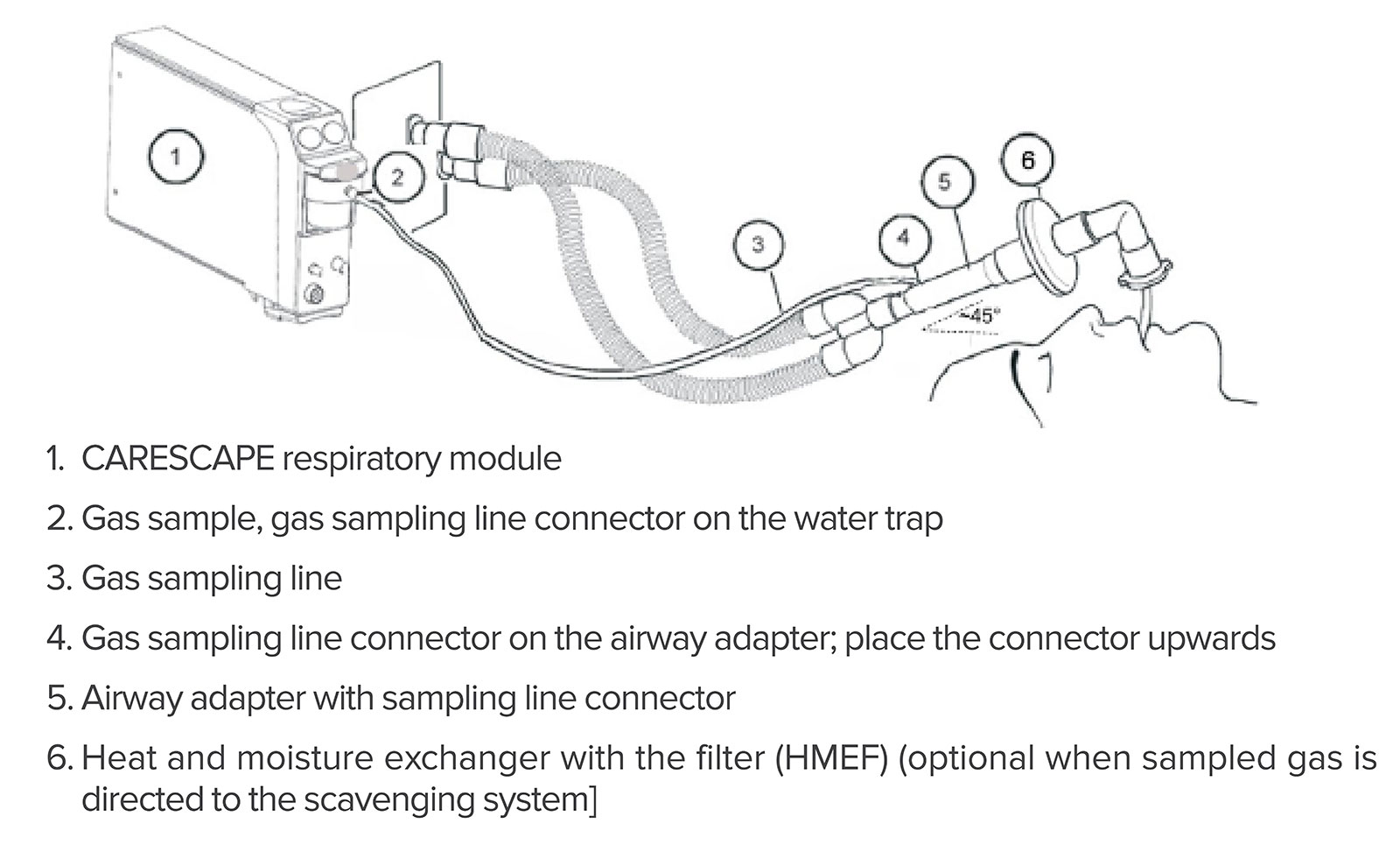
Figure 5: Gas Measurement Setup.
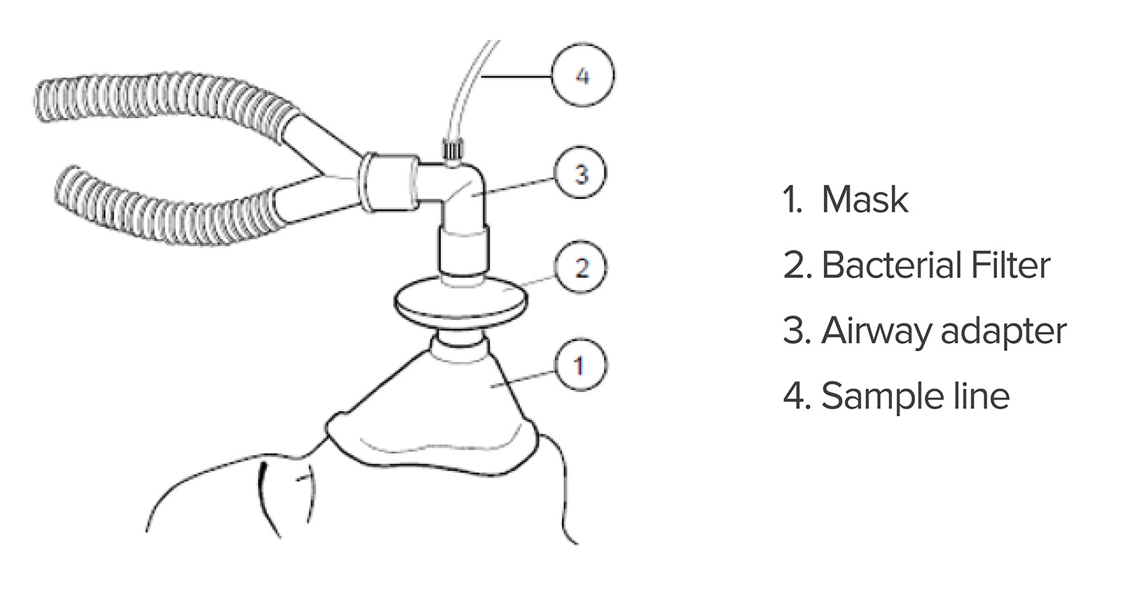
Figure 6 – Gas Measurement Setup during mask ventilation.
Returning to the original report, even though it seemed that emptying the condenser reservoir corrected the gas concentration measurements, we could not simulate nor explain how the water accumulation could cause a combination of increased FiCO2, and low FiAA, and low FiO2 compared with the set values. Measuring gas and anesthetic concentrations lower than the set values typically results from either low fresh gas flow or leaks in the gas sampling setup. When fresh gas flows are low enough to cause significant rebreathing, patient uptake of anesthetic and oxygen will result in low measured exhaled agent and O2 concentrations compared with the set values. Leaks in the gas sampling setup cause dilution of sampled gas which is possible in this case since FiO2 readings of 21% are identical to room air. Increased FiCO2 is typically caused by either high apparatus dead space or waning effectiveness of CO2 absorbent.
Despite extensive testing, GE Healthcare cannot provide a verified explanation of the reported observations. Following recommended procedures for managing humidity and accumulated water in the breathing system should minimize any related problems. The recommendations summarized in this report should be a useful guide and users can always refer to the instructions for use or contact GE Healthcare directly with questions: www.gehealthcare.com/about/contact-us
Sincerely,
Tim McCormick
Chief Engineer—Anesthesia & Respiratory Care, GE HealthCare
The information provided is for safety-related educational purposes only, and does not constitute medical or legal advice. Individual or group responses are only commentary, provided for purposes of education or discussion, and are neither statements of advice nor the opinions of APSF. It is not the intention of APSF to provide specific medical or legal advice or to endorse any specific views or recommendations in response to the inquiries posted. In no event shall APSF be responsible or liable, directly or indirectly, for any damage or loss caused or alleged to be caused by or in connection with the reliance on any such information.
