The information in this column is provided for safety-related educational purposes only, and does not constitute medical or legal advice. Individual or group responses are only commentary, provided for purposes of education or discussion, and are neither statements of advice nor the opinions of APSF. It is not the intention of APSF to provide specific medical or legal advice or to endorse any specific views or recommendations in response to the inquiries posted. In no event shall APSF be responsible or liable, directly or indirectly, for any damage or loss caused or alleged to be caused by or in connection with the reliance on any such information.
How Do Flow Sensors Work?
Dear SIRS:
We have just installed new GE Aisys anesthesia machines that use the 7900 SmartVent®. This ventilator uses 2 breathing circuit flow sensors, which have a pressure sensor tube on each side of a small mylar flap. I understand how a pressure drop over a fixed resistance can be used to calculate flow, but this is a variable resistor because the flap opens as flow increases. So how does this thing work? In other words, how do they calculate flow given both a pressure variable and a variable resistance? ARRRGGHHHHH!!!!
James F. Szocik, MD
University of Michigan
In Response:
Dear Dr. Szocik,
Flow sensors are a critical monitoring and feedback-regulating component of modern anesthesia machine ventilators, and this type is common to many of the GE-Datex machines. Dräger Medical, Inc., and Datascope, Inc., on the other hand, utilize a different type of flow sensor (a hot-wire anemometer, e.g., in Fabius®, Apollo®, and Anestar® machines.) This question about the GE variety originally appeared in the Society for Technology in Anesthesia (STA) listserv, with numerous responses from their membership. With their permission to reproduce this question, and to expand the understanding of flow sensor technologies, we asked the experts from GE Healthcare and Dräger Medical to enlighten us. I have included some additional questions for them to consider: How is the information used by the ventilator, with particular regard to the inspiratory versus expiratory sensor? Under what conditions has this technology failed, or is likely to fail?
Michael A. Olympio, MD
Chair, Committee on Technology
In Response:
Dear Dr. Szocik,
Various technologies are used to measure airway gas flow and volume deliveries. These include pneumotachometers, hot wire anemometers, rotating vane spirometers, and ultrasound flowmeters. Each of these technologies offers different benefits and drawbacks depending on their underlying property used to detect flow.
A pneumotachometer uses a restrictor in the gas flow passage to create a pressure drop that can be sensed by a differential pressure transducer. (Note: It is the difference and not the pressure from each side of the orifice that is being measured.) Each output signal from the pressure transducer consistently represents a unique gas flow rate, and is calibrated to accurately report the measurement in gas flow rate. An orifice is a simple and inexpensive construction for a flow restrictor. The disadvantage of a fixed orifice is its non-linear relationship between the differential pressures and the gas flow rates. The size of the fixed orifice is a compromise between a tolerable flow resistance at high flow rates, and adequate obstruction to create detectable differential pressures at low flow rates. If the selection of orifice size favors the low flow sensitivity, the pressure transducer runs out of measurement range at high flows. If the orifice size favors high flow range, the pressure transducer would not receive detectable signal for measurement sensitivity at the low flow rates. The necessary compromise in measurement range also affects computation of patient tidal and minute volumes, which are derived by integrating gas flows in the airway. The demand for large flow range measurement is needed to cater to size of patients. Fixed orifice sensors require separate flow sensors for adult and pediatric patients. The variable orifice flow sensor elegantly solves this problem, allowing a single sensor for adults, pediatric patients, high flows, and low flows.

Figure 1. GE Healthcare flow sensor. In response to increasing gas flow, the flapper of the variable orifice opens more widely to decrease resistance to flow, thereby straightening the differential pressure vs. flow response.
The 7900 Smartvent® in the Aisys®, Avance®, Aespire®, and Aestiva® Anesthesia System uses a single restrictor comprised of a variable orifice to measure gas flows in both pediatric and adult patients. Variable orifice flow sensing technology dates back to the 1930s, but its practical adoption as airway flow meters began many decades later with a flap that opens with increase gas flows (Figure 1). The 7900 Smartvent® flow sensors are available in a Mylar or stainless steel material. The former can be used in Magnetic Resonance Imaging (MRI) suites in conjunction with the Aestiva® MRI anesthesia system. The stainless steel flow sensors are autoclavable, and are designed for long-term use.
At very low flows, the flap is in its natural state to form a small slit orifice. This small orifice allows an easily measurable differential pressure signal to be generated despite the low flow. As the gas flow increases, the flap opens more, reducing resistance to gas flow. At a given flow rate, the differential pressure across the deflected (more open) flap is lower than at its natural position. As in a fixed orifice, there is a one-to-one correspondence between each flow rate and the pressure drop that it creates. This allows the differential pressure measurement to be uniquely converted to the gas flow rate. Furthermore, the variable orifice straightens the pressure-flow characteristic to provide linear and uniform measurement sensitivity through its measured range.
While each individual variable orifice is unique and consistent, they differ slightly from transducer to transducer. To keep the tight specified accuracy, each transducer is individually calibrated in each direction of gas flow, and the calibrated table is electronically stored in the variable orifice connector. The 7900 Smartvent® “reads” the calibration table and converts the measured differential pressures across the variable orifice to the flow rates. The flow sensor is also corrected for variations in gas composition, altitude, and circuit pressures to provide accuracy in clinical use.
The 2 variable flow sensors provide many useful features to deliver and monitor patient ventilation. Fresh gas flow to, and gas compression in, the Anesthesia Breathing System change the gas volume delivered by the ventilator flow valve to the patient. The 7900 Smartvent® uses the inspiratory flow sensor to measure the inspired tidal volume and compensate breath-to-breath the inspired tidal volume delivery to match the user setting. This flow sensor is also sensitive in detecting small flow rates, as low as 200 ml/min, at the start of a breathing effort to trigger a synchronized assisted or supported breath in spontaneously breathing patients, including neonates. In addition, the ventilator computes tidal and minute volumes from the flow measurement. They are used to detect low minute ventilation and apnea. Its ability to detect bidirectional flow is used to monitor unexpected flow reversal, such as caused by a stuck open inspiratory or expiratory check valve, in the Anesthesia Breathing System.

Figure 2a. External view of the GE Healthcare Off-set flow sensor for use in moist airways gas passages.
Tidal volumes and minute ventilation obtained from the expiratory flow sensor are used to detect and alarm on low minute ventilation and apnea. This flow sensor also acts as a safety check to constantly monitor the appropriate volume delivered by the ventilator, and alarms when the expired gas volume varies significantly from the setting. Such variations may be caused by leaks or valve or flow sensor issues. Moisture is an inherent by-product of carbon dioxide absorption in the circle breathing system, especially in low flow anesthesia practice. Moisture may cause small beads of water or a foggy appearance in the flow sensor, which does affect performance. Pooled water in the flow sensor or water in the sensing lines could result in false readings. The Off-set Flow Sensor (Figure 2a) is designed to address this issue by adding taper and grooves in the sensor housing to channel water away from the affected areas, as shown in Figure 2b. The Off-set flow sensor allows the use of the flow sensors in high humidity, without resorting to system heating.
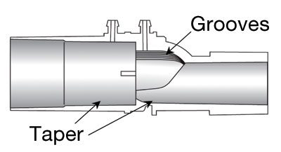
Figure 2b. Cut away view of Off-set flow sensor body showing the taper and grooves design.
We hope that this brief answers your question and highlights the practical and beneficial use of our dual breathing circuit flow sensor in patient ventilation during anesthesia.
Robert Tham, PhD
Advanced Technology Group
GE Healthcare, Life Support Solutions
Michael Oberle
R&D Manager—Anesthesia Systems
GE Healthcare, Life Support Solutions
General References
- Osborn JJ. A flowmeter for respiratory monitoring, Crit Care Med, 1978; 6: 349-351.
- Avance User’s Reference Manual (M1077716), 2007. Datex-Ohmeda, Inc, a General Electric Company.
- EXPLORE! Aisys®, 2005. Datex-Ohmeda, Inc, a General Electric Company.
In Response:
Dear Dr. Szocik,
We thank the editor for the opportunity to respond to this general topic. As the technology for the instrumentation of our anesthesia systems and monitors has improved, our trust and reliance upon the data that the sensors provide has risen in relation. Drs. Szocik and Olympio make a valuable observation that we should understand the behaviors and limitations of the technology, otherwise we run the risk of misinterpreting the situation presented. The anesthesia machine, ventilator, or monitor relies upon the information that it receives from the sensor technologies employed.
The measurement of respiratory gases in anesthesia has to take into account not only the gas mixture, which changes during the procedure, but also changing airway pressures and humidity. Water vapor in the respiratory gases is an inevitable reality in the OR. Indeed, it is desirable to humidify and warm the fresh gas prior to it being delivered to the patient. In order to minimize the impact of water vapor on the breathing system and the respiratory gas measurement, Dräger Medical many years ago decided the best approach was to maintain the water as vapor rather than allow it to condense out in the absorber system, which is typically the coldest part of the gas path. This removes the historical limitation for the use of low and minimal fresh gas flow techniques.
The hot-wire anemometer used by Dräger in the current range of anesthesia devices has the characteristic of being insensitive to water vapor and has a very low resistance and no moving parts. The sensor works by measuring the cooling effect of the gas passing over a thin, heated wire. The higher the cooling effect, the higher will be the flow of gas. In order to be accurate, the sensor needs to know the density of the gas, which is provided to the measurement system by the gas analysis data. This same technology is used internally in the GE Aisys® anesthesia machine for the measurement of fresh gas flow as well as in many other industries including aeronautics where the hot wire anemometer has become the standard for air speed measurement in aircraft.
Robert Clark MEng, MBA
Director of Marketing, Perioperative Care
Dräger Medical, Inc.
Telford, PA, USA
